Facilities
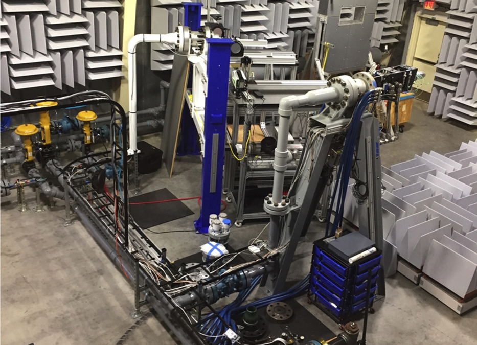
Multi-stream control valves and piping.
ARL:UT
ARL:UT is a University Affiliated Research Center (UARC) located at the J. J. Pickle Research Campus (PRC) in northwest Austin, Texas, approximately eight miles from the main campus. ARL:UT has a long history of work in the areas of electromagnetics, acoustics, communications, radar, and sonar. Over the years, a large number of prototype systems have been built by ARL:UT that have been used by the U.S. Navy and Army. The facility has an extensive machine shop with numerically controlled mills, lathes, welding shops, and coordinate measurement machines. ARL:UT also operates facilities that provide metal fabrication, metal conversion coating, pressure testing, acoustic testing, sonar calibration, and transducer fabrication and repair for complex underwater acoustic arrays and electronics housings. ARL:UT facilities have extensive computer processing and high networking capability, a satellite ground control station, a high pressure gas delivery system for high speed flow research, and a GPS monitor ground station.
Gas Dynamics Laboratory
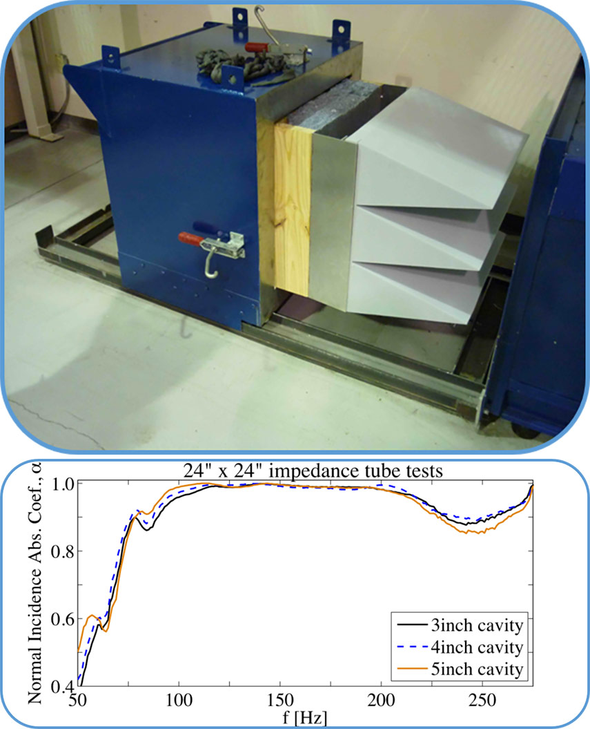
The Gas Dynamics Laboratory is located within the confines of ARL:UT at the J. J. Pickle Research Campus. The facility is designed to provide a controlled environment for conducting high fidelity experiments of fluid flows as it relates to aerospace systems of practical importance to U.S. government agencies such as NASA, the Department of Defense, and the Department of Energy. The majority of the infrastructure is intended to accommodate laboratory scale systems concerned with high-speed gas dynamics (high subsonic to hypersonic flow regimes) and aeroacoustics. Pressurized gas is delivered to any one of the four independently operated test stands that are housed within the anechoic structure. A plan view of the GDL facility is provided in Figure 1 and comprises interior dimensions (wedge tip to wedge tip) of 46ft(L) x 28ft(W) x 25ft(H). The floor and walls of the facility are treated with various layers of acoustic sound absorbing material that produce a combined measured normal incidence absorption coefficient of 99% above 100Hz. Sound absorption characteristics of the anechoic wedge are based on impedance tube tests conducted in October of 2009 by Jeff Schmitt, Mike Black, Einar Ristroph, and John Phillips at ETS-Lindgren, a privately owned company located in the Austin area. An illustration of the test apparatus at ETS Lindgren is shown in Figure 2a alongside the resultant absorption curves from the study in Figure 2b.
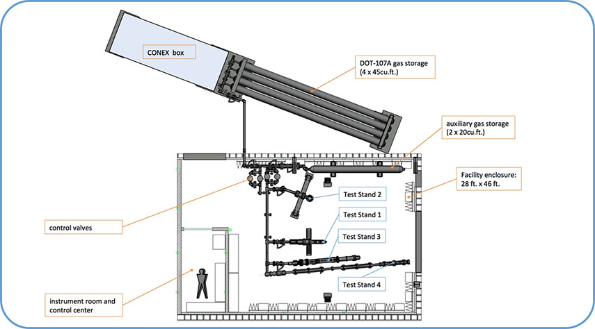
Figure 1: Plan view of Gas Dynamics Laboratory test facility at ARL:UT
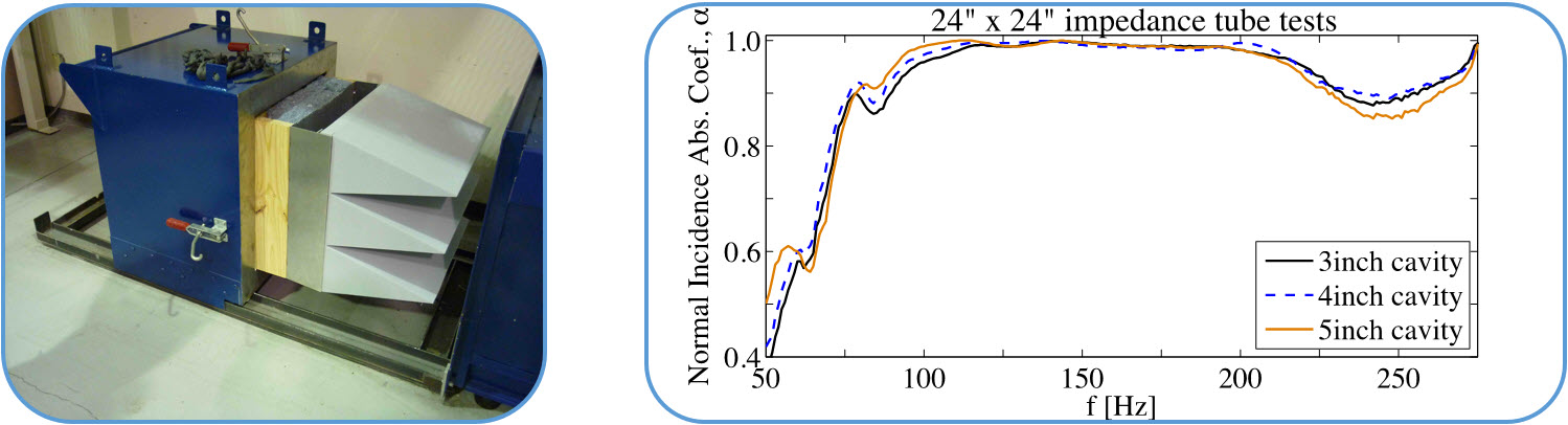
Figure 2: (a) Impedance tube test apparatus at ETS-Lindgren in 2009. (b) Measured normal incidence sound absorption coefficient of GDL anechoic wedge.
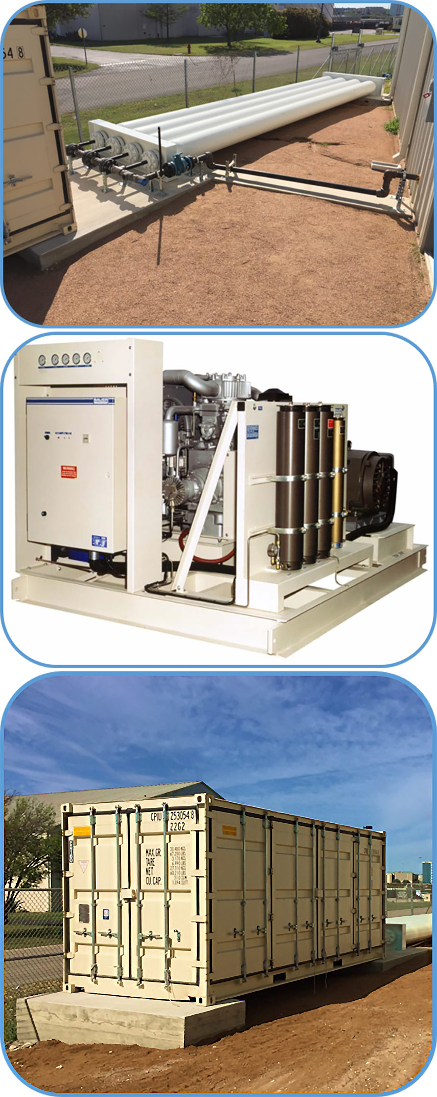
The compressed air system functions as a blow down type with pressurized gas being stored in four DOT-107A pressure vessels comprising 180 cubic feet of water volume storage at 2,100 psig (see Figure 3a). Compressed air is provided by way of a four stage, 100 horsepower Bauer compressor (model I280-100-E3 shown in Figure 3b) that outputs 103 SCFM at 500 psig (86 SCFM at standard inlet conditions). The discharge pressure of this compressor is 5kpsi. For most tests, the working fluid is unheated air (total temperature around To = 304 K, ratio of specific heats, γj = 1. 4, specific gas constant of air, R = 287. 05 J/kg/K), although a pair of auxiliary pressure vessels (20 cubic feet of water volume storage per vessel) is available to accommodate other gas types (helium, pure nitrogen, etc.). These auxiliary gas storage tanks are located inside the GDL facility, as shown in Figure 1.
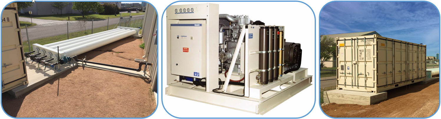
Figure 3: (a) DOT-107A external gas storage. (b) 100 HP Bauer compressor. (c) CONEX box for compressors
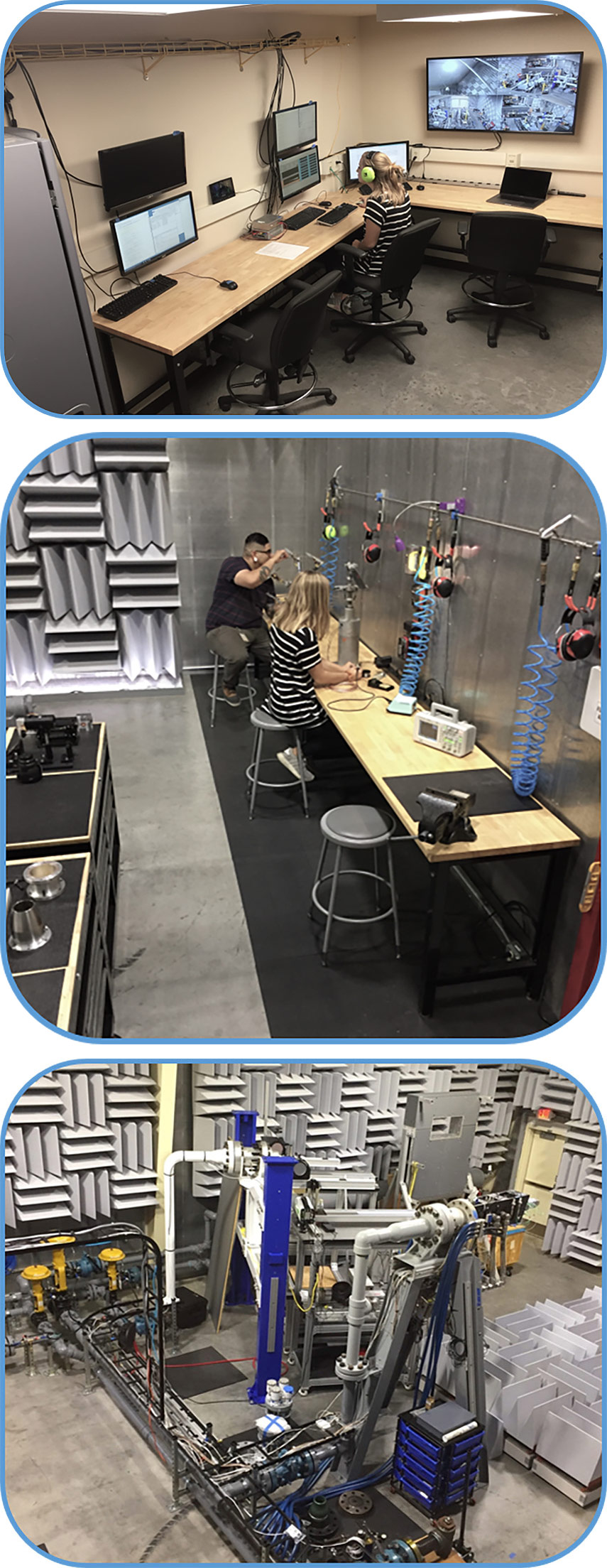
The operating conditions of each of the four test stands (nozzle pressure ratio and temperature ratio) are monitored and controlled using a National Instruments CompactRIO system capable of reducing variations in the set point to less than 1% over extended periods of time. Sensitive instruments are stored in a clean room where the control center is located, as shown in Figure 4a. Various workstations with immediate access to shop air and electronics equipment are also available for performing diagnostics (Figure 4b). Another unique feature of the GDL is that the compressed gas storage system, piping and control valves can accommodate two separate gas streams as shown in Figure 4c. This capability allows dual-stream flows, made up of two unique gas species, to be studied. A description of some of the testing capabilities in the GDL are provided in various archival papers and publications:
- Donald, Baars, Tinney, Ruf (2014),
Sound produced by large area ratio rocket nozzles during fixed and transient operations,
AIAA Journal, Vol. 52, No. 7. - Baars, Tinney, (2014)
Shock-structures in the acoustic field of a Mach 3 jet with crackle,
Journal of Sound & Vibration, Vol. 333. - Canchero, Tinney, Murray, Ruf (2016)
Flow and acoustics of clustered rockets during startup,
AIAA Journal, Vol. 54, No. 5. - Tinney, Valdez (2018)
A new test stand for measuring wall shear stress,
AIAA Paper 2018-2085. - Valdez, Tinney (2018)
Measurements of a Mach 3 jet using high-speed optical techniques,
AIAA Paper 2018-3148. - Tinney, Valdez, Murray (2020)
Aerodynamic performance of augmented supersonic nozzles,
Experiments in Fluids, Vol. 61, No. 48
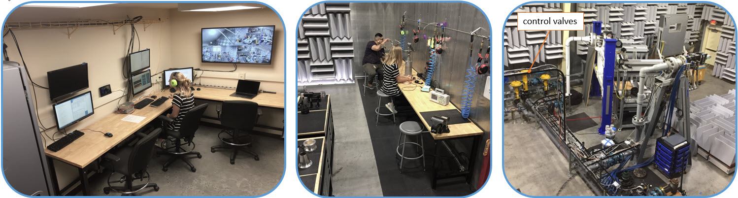
Figure 4: (a) Clean room and control center. (b) Work stations. (c) Multi-stream control valves and piping.