Multi-Stream Flow Thrust Stand
GDL's thrust stand
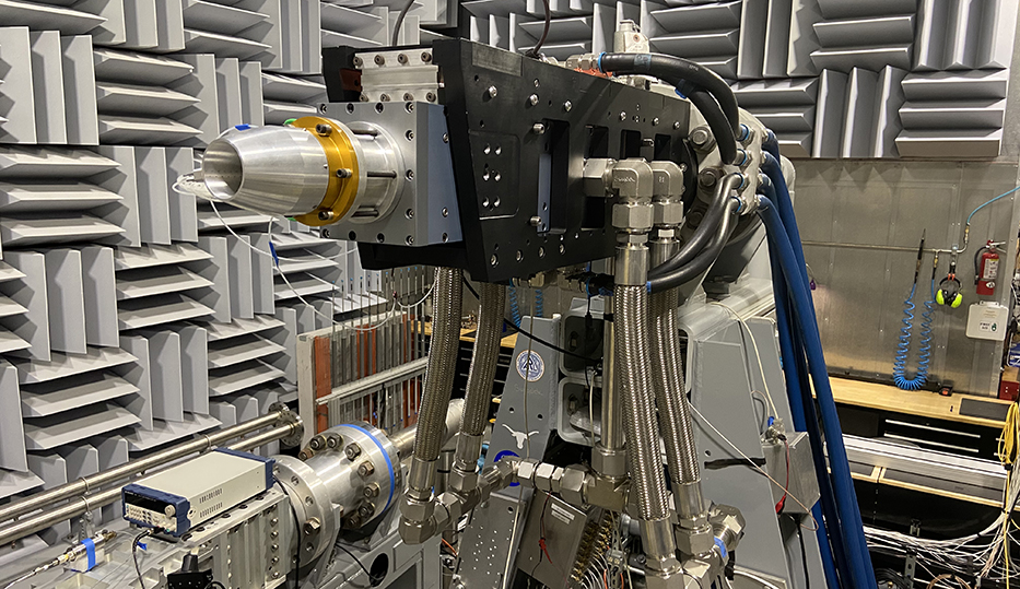
The GDL thrust stand at ARL-UT was designed to accommodate multi-stream nozzles and employs the scale-force measurement technique. An image of the thrust stand is shown in Figure 1a. The plenum is attached to a stiff outer cage using several notch-type flexures with sharp corners. Axial forces produced by the nozzle are sensed by a Micro-Epsilon CS05 capacitive displacement sensor (CD) with 6110 control box that measures the displacement of the floating plenum relative to the stiff outer cage. The dynamic range of the CD sensor is 0.50 mm with 50 nm accuracy (0.01% of FS). Notch thickness is chosen to maximize the CD sensor’s output (0 to 10 volts), all the while confining the maximum allowable material stresses of the notch flexures to 50% of their yield strength. Additional details of this thrust stand are provided by Valdez & Tinney (2016).
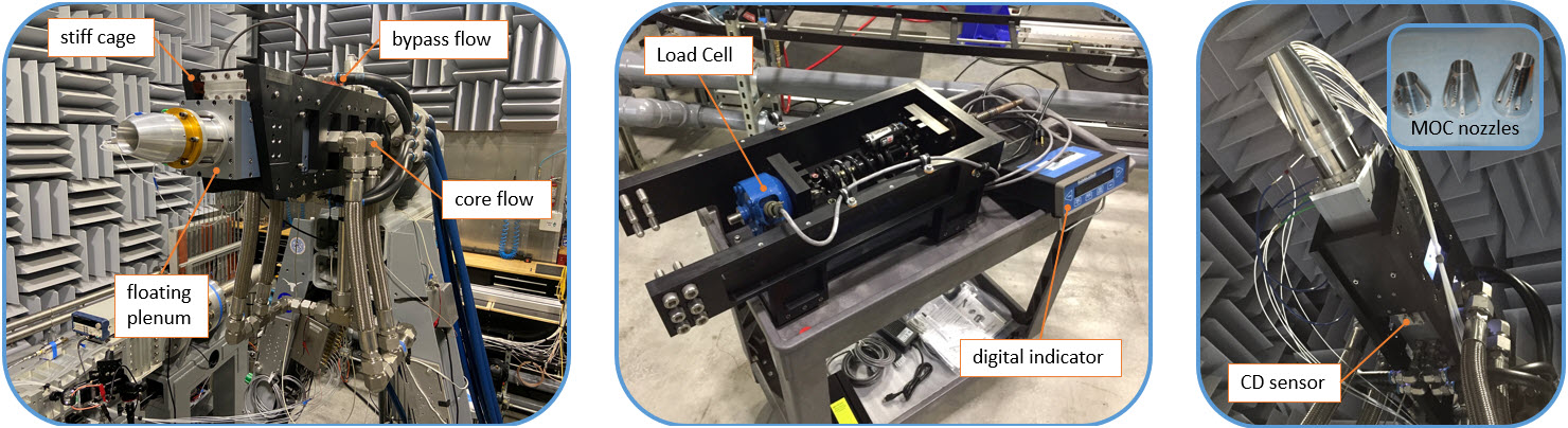
Figure 1: (a) Multi-Stream Flow Thrust Stand. (b) Detachable calibration stand. (c) Calibration with a Mach 1.7 MOC nozzle.
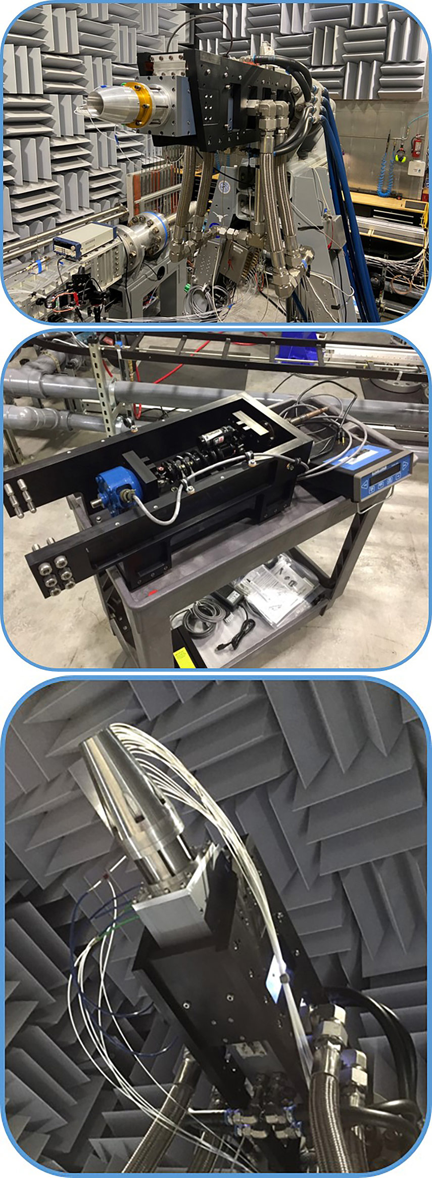
Calibrations are performed several ways. The first comprises static calibrations using the detachable calibration stand shown in Figure 1b that mounts to the end of the plenum. This is achieved by placing a blind flange on the end of the plenum that the nozzles normally mount to. This blind flange seals the plenum to isolate the affect of elevated plenum pressures; elevated pressures cause the plenum walls and flexible hoses to expand and must be accounted for. The load cell used for these static calibrations is a calibration grade model 1800 Platinum Standard ® manufactured by Interface. Load cell readings are provided by a model 9840 high-speed digital indicator. Factory calibration is performed with both the load cell and digital indicator combined, which results in a precision error band of 0.02%.
Static calibrations of the thrust stand are performed by incrementally increasing the plenum pressure from zero gage pressure to NPR† = 3.42 in increments of δNPR† = 0.38. Note that NPR† is defined as the nozzle pressure ratio relative to the design pressure ratio of the nozzle. At each pressure setting, the load cell is then pushed up against the blind flange and a set of conversion coefficients from a second order least squares fitting of the load cell (force) versus CD sensor voltage (displacement) is gathered. A sample static calibration curve, at one of the pressure settings, is shown in Figure 2a. Calibration coefficients from each of the plenum pressure increments are then estimated using a third-order least squares fit that allows corrections for elevated plenum pressures as shown in Figure 2b. A comparison between linear and high-order (3rd order) estimates of the conversion coefficients is shown in Figure 3a. Higher-order estimates are shown to provide a better overlay of the measured data, relative to a linear estimate. The maximum hysteresis error is shown to be ±1 % at F† = 1 while percent drift at F† = 0.0 is within ±0.5 % of the maximum reading. F† is defined as the measured thrust divided by the thrust produced at the design pressure ratio of the nozzle. An average of the hysteresis error, for the same loading and unloading conditions, reduces the precision error of the conversion coefficients to 0.06 % as shown in Figure 3a. The root sum of squares errors of the precision errors is then used to summarize the total error in the thrust sensing system, based on static calibrations. Precision errors corresponding to the pressure sensing system, CD sensor, load cell, and data conversion result in a total estimated error of 0.08%.
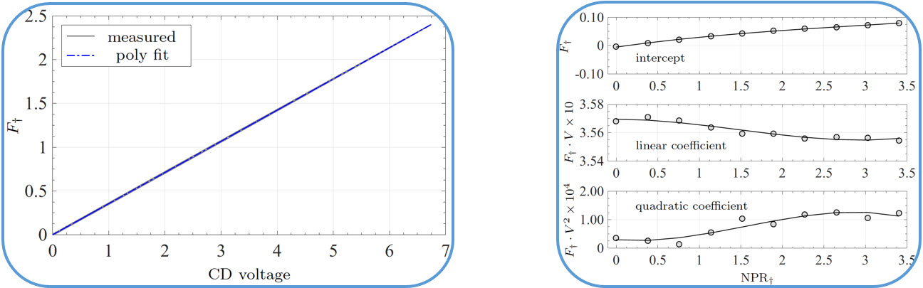
Figure 2: (a) Static calibration of thrust sensing system. (b) Higher-order least squares fit of the calibration coefficients.
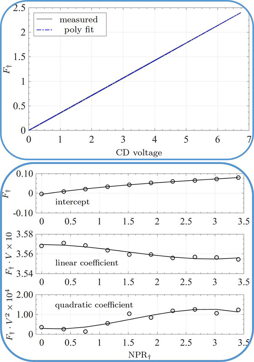
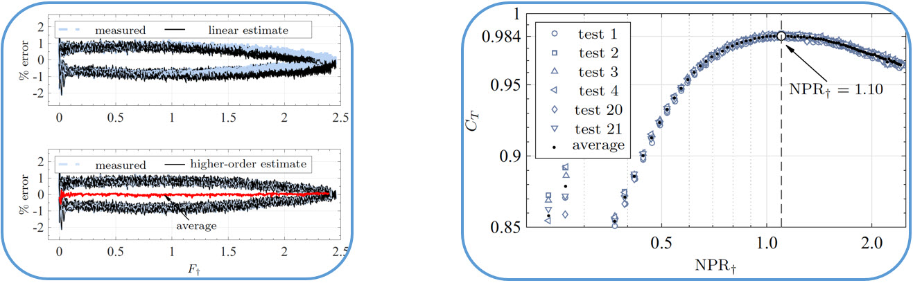
Figure 3: (a) Comparison between measured and estimated axial thrust. (b) Thrust coefficient of the Mach 1.7 MOC nozzle.
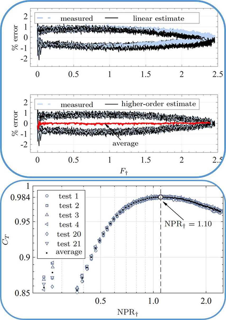
The second method for calibrating the thrust stand is to measure the thrust from nozzles with known thrust values. This is performed at the start and end of each test campaign to identify drift in the measurement apparatus due to instrument errors or temperature effects. The current inventory comprises three nozzles covering Mach numbers of 1.3, 1.7 and 2.0, as shown in Figure 1c. These nozzles act as the thrust standard, whose contours were designed using a method of characteristics (MOC) computer program for axisymmetric nozzles. The total temperature of the supply air is recorded for each run and results in a drift in the CD sensor between the start and end of each test between 0.08% and 0.30%. The axial thrust produced by the Mach 1.7 MOC nozzle is shown in Figure 3c.
- Valdez, Tinney, (2016),
A new thrust stand for testing multi-stream and heat simulated supersonic nozzles.
54th AIAA Aerospace Sciences Meeting, San Diego, USA, Paper 2016–1890. - Tinney, Valdez, Murray, (2020)
Aerodynamic performance of augmented supersonic nozzles.
Exp. Fluids, Vol. 61, No. 48, DOI: 10.1007/s00348-019-2866-3.